Manufacturers across aerospace, automotive, energy, and medical sectors increasingly face tighter tolerances, complex geometries, and stringent documentation requirements. To keep pace without sacrificing throughput, many are adopting inline metrology and industrial computed tomography (CT) to verify quality earlier, faster, and more comprehensively. By shifting from end‑of‑line inspection to in‑process verification, organizations can raise first‑pass yield (FPY), reduce scrap and rework, and accelerate release to production.
What Is Inline Metrology?
Inline metrology refers to measurement systems integrated within production lines that verify critical dimensions and features without removing parts from the flow. Unlike offline checks—where components are sampled and transported to a metrology lab—in‑process systems deliver immediate feedback to machines, operators, and quality systems.
Common inline modalities include:
- Contact probing (touch trigger, scanning probes) on machine tools or dedicated stations.
- Optical/laser scanning for dense point clouds and full‑field comparison to CAD.
- Structured light and stereo vision for high‑speed 3D feature extraction.
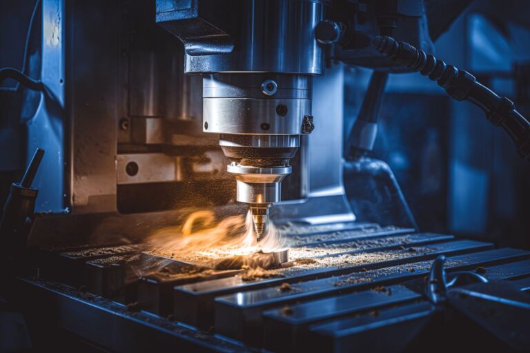
- On‑machine measurement (probing and tool setters) to verify set‑ups, compensate tool wear, and prevent non‑conforming runs.
What Is Industrial CT?
Industrial CT uses X‑rays to reconstruct a 3D volumetric model of the part, capturing internal and external geometry in a single scan. CT complements surface‑based methods by revealing:
- Internal features (channels, lattice structures, porosity) that are otherwise inaccessible.
- Assembly interfaces and hidden defects such as voids, inclusions, cracks, lack of fusion, or incomplete penetration in welds.
- Wall thickness, fiber orientation (for composites), and density variations.
For complex parts—lightweight castings, AM lattice components, multi‑material assemblies—CT often becomes the fastest path to design validation and production approval.
Why Inline + CT Improves First‑Pass Yield
- Detect earlier, fix sooner: In‑process checks catch drift (tool wear, thermal growth) before lots accumulate defects.
- Close the loop: Measurement deltas can drive automatic offsets in CNCs/robots, stabilizing processes over shifts and batches.
- 100% verification where it matters: Critical characteristics can be measured on every part, not just sampled.
- Fewer false accepts: Full‑field comparison to CAD reduces the risk of passing marginal parts.
- Traceability by design: Measurements are tied to serial numbers and process parameters, simplifying audits and PPAP/FAI documentation.
Core Technologies & When to Use Them
- On‑Machine Probing: Setup verification, in‑cut part location, feature checks on prismatic parts; ideal for reducing scrap at changeovers.
- Laser Line/Structured‑Light Scanners: Rapid, non‑contact coverage of freeform surfaces (e.g., turbine blades, medical housings) with color‑map deviation to CAD.
- 2D/3D Vision with AI: High‑speed classification of surface defects (burrs, pits, weld spatter) and gauging of edges/holes in stampings and sheet‑metal assemblies.
- Industrial CT (Cone‑Beam or Fan‑Beam): Internal geometry, porosity analysis, wall‑thickness mapping, and dimensional metrology for cast, molded, AM, or welded components.
Designing for Metrology: Principles That Pay Off
- Datum strategy: Clear primary/secondary datums that are accessible to inline sensors.
- Feature accessibility: Keep critical characteristics visible (or CT‑addressable) without complex fixtures.
- Tolerancing: Use GD&T with measurement in mind (profile, position, runout) and align specs with achievable gage R&R.
- Measurement Systems Analysis (MSA): Validate precision and bias; target %GRR < 10% for critical features.
Data & Integration: Building the Digital Quality Loop
- SPC in real time: Stream results into SPC to monitor Cp/Cpk and trigger alarms before non‑conformance.
- CAD‑to‑Inspection automation: Auto‑generate inspection plans from PMI (product manufacturing information) to reduce programming time.
- Feedback to CAM/PLC: Apply offsets to tool wear, fixture compensation, or robot paths based on deviation trends.
- Unified data backbone: Connect metrology to PLM/MES/QMS with version control and e‑signatures for compliance.
Key KPIs to Track
- First‑Pass Yield (FPY) and Cost of Poor Quality (COPQ)
- Scrap/Rework rates and PPM (defects per million)
- Cycle time impact of inline checks vs. offline sampling
- Cp/Cpk for critical characteristics
- False‑reject rate (Type I) vs. false‑accept risk (Type II)
Industrial CT: Practical Considerations
- Resolution vs. part size: Voxel size scales with geometry and source/detector; target a voxel size ≤ 1/10 of the tolerance as a rule of thumb.
- Material & thickness: Denser or thicker sections may require higher kV/mA or longer scans; consider region‑of‑interest scans to save time.
- Calibration & artifacts: Correct for beam hardening, scatter, and ring artifacts; use traceable phantoms for dimensional accuracy.
- Safety & compliance: Shielding, interlocks, and operator training are essential when implementing CT inline or near‑line.
Implementation Roadmap (Inline & CT)
- Pick a high‑impact part family: Castings, AM parts, or multi‑step machined components with frequent rework.
- Define Critical‑to‑Quality (CTQ) features: Rank by risk and cost of failure.
- Select the right sensor mix: Combine on‑machine probing with optical/vision or CT where internal features are critical.
- Pilot a closed‑loop cell: Enable automatic offsets; measure FPY and scrap before/after.
- Standardize & scale: Template inspection plans, fixtures, and data flows for rapid replication to new lines and plants.
Use Cases
- Die‑cast housings: Inline vision + near‑line CT for porosity and wall thickness—fewer leaks, faster PPAP.
- Additive metal parts: CT for internal channels/lattices; surface scan to verify supports removal and final geometry.
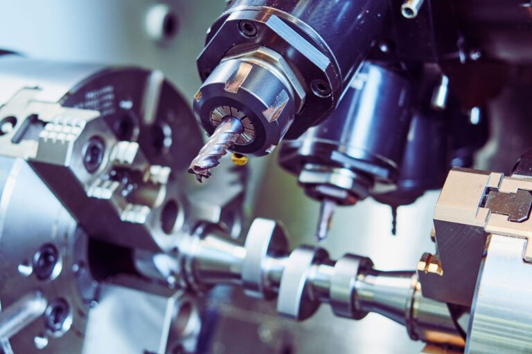
- Precision machining: Probing for set‑up, optical scan for profile, CMM audit at milestones; offsets driven by deviation trends.
- Welded assemblies: AI vision for bead continuity and spatter, CT sampling for penetration/lack‑of‑fusion validation.
Looking Ahead
Expect faster sensors, edge computing, and physics‑informed AI to push more verification in‑process, with automated decisions that stabilize quality while lines run. CT is becoming more compact and production‑friendly, enabling hybrid cells where internal and external checks occur in one flow.
At SL Industries, we closely follow—and selectively adopt—inline metrology and industrial CT practices that demonstrably improve first‑pass yield, traceability, and speed to validation, helping manufacturers deliver reliable components for demanding applications.