Why individually correct parts can still create assembly problems
In large fabricated assemblies, dimensional quality cannot be judged only by checking individual parts or isolated measurements. A plate, bracket, bore, mounting face, or subassembly may each fall within its specified tolerance, while the completed structure still fails to align correctly during machining or final assembly.
This happens because dimensional variation accumulates across connected features. Small deviations in cutting, fit-up, welding, positioning, and machining can combine into a larger functional error at the final interface. The individual results may appear acceptable when reviewed separately, but their combined effect can create misaligned holes, uneven gaps, insufficient machining allowance, or difficulty connecting the fabrication to the customer’s equipment.
For OEMs and heavy fabrication suppliers, tolerance stack-up is therefore not only a drawing issue. It is a production planning, inspection, and assembly-readiness issue.
1) What tolerance stack-up means in fabricated assemblies
Tolerance stack-up describes the cumulative effect of permitted dimensional variations across a chain of related features. Every manufactured dimension has some allowable deviation. When several dimensions contribute to the location or orientation of a critical interface, their individual variations combine.
In a large fabricated component, the dimensional chain may include:
- cut part dimensions
- plate thickness variation
- fit-up gaps
- bracket positions
- weld shrinkage
- angular distortion
- accumulated subassembly dimensions
- machining allowances
- final hole or bore locations
- relationships between mounting faces
The resulting assembly condition depends not only on whether each feature passes inspection, but also on the direction and combination of the deviations.
For example, several brackets may each be positioned within their individual drawing tolerances. If the deviations all occur in the same direction, however, the final mounting pattern may no longer align with the mating component.
2) Why local conformity does not guarantee functional conformity
A dimension can be locally acceptable without supporting the intended function of the full assembly. This distinction is important in heavy fabrication, where the customer is often concerned less with individual plate dimensions and more with whether the completed structure fits, aligns, and performs as required.
Local conformity answers questions such as:
- Is this bracket within its positional tolerance?
- Is this plate cut to the specified length?
- Is this bore diameter acceptable?
- Is this mounting face sufficiently flat?
Functional conformity asks broader questions:
- Will all mounting points align with the customer’s assembly?
- Will two distant bores remain coaxial?
- Will the fabricated frame sit correctly on its supporting structure?
- Is sufficient material available for final machining?
- Will connected subassemblies fit without forced alignment or rework?
A fabrication may pass multiple local checks and still fail one of these functional requirements. That is why inspection plans must consider relationships between features, not only isolated dimensions.
3) Why the risk increases with component size and complexity
Tolerance accumulation becomes more difficult to control as the size and complexity of the fabrication increase. Long distances magnify angular deviations, while multiple welds and interfaces create more opportunities for variation to enter the assembly.
Large fabricated structures may include:
- several welded subassemblies
- repeated brackets or mounting points
- long structural members
- multiple machining interfaces
- hole patterns distributed across several metres
- components manufactured in different production stages
- features inspected from different reference points
A small angular error near one end of a long structure may produce a significant positional difference at the other end. Similarly, a minor deviation repeated across several connected components can result in a final interface that falls outside the functional assembly window.
Large components are also more difficult to reposition and rework. If tolerance accumulation is discovered only during final assembly, the correction may require machining, cutting, welding repair, straightening, or modification of several related features.
4) The importance of a clear datum strategy
Datums provide the reference system from which dimensions are established, manufactured, and inspected. In complex fabrications, an unclear or inconsistent datum strategy is a common source of dimensional conflict.
Problems occur when different teams or production stages use different reference assumptions. Fabrication may position features from one edge, inspection may measure from another surface, and machining may establish a new reference based on the actual condition of the welded structure.
Each activity may be internally consistent, but the final interfaces may not relate correctly to one another.
A practical datum strategy should define:
- the primary functional reference
- secondary and tertiary orientation references
- which interfaces must remain related
- how subassemblies are located before welding
- how welding movement may affect the references
- which datums will be used during machining
- how final inspection will confirm functional relationships
The most useful datums are usually those connected to how the component will be assembled or used, rather than simply the easiest surfaces to measure.
5) How welding affects the dimensional chain
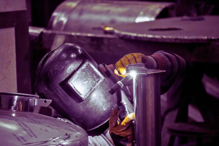
Welding introduces thermal expansion, shrinkage, and residual stress. These effects can change distances, angles, straightness, and alignment after initial fit-up has been completed.
Even when individual welds meet quality requirements, their cumulative effect may alter the final geometry. This is especially important when multiple welds influence the same functional interface.
Welding-related contributors to tolerance stack-up include:
- transverse and longitudinal shrinkage
- angular distortion
- movement after restraints are released
- sequence-dependent dimensional change
- unequal heat distribution
- local deformation around attachments
- interaction between welded subassemblies
This does not mean that welding movement can always be eliminated. The practical objective is to anticipate its likely effect, reserve suitable adjustment or machining allowance, and inspect the structure at stages where corrective action remains possible.
6) Hole patterns, bores, and mounting faces require relational control
Distributed hole patterns and aligned bores are particularly sensitive to tolerance accumulation. Checking each hole individually may confirm its diameter and local position, but the assembly may still fail if the overall pattern does not match the mating structure.
The same principle applies to:
- bearing seats that must remain coaxial
- mounting faces that must be parallel
- interfaces located on opposite sides of a frame
- brackets that must share a common plane
- guide features that must remain aligned over long distances
- bolted connections distributed across separate subassemblies
These features should be evaluated as functional groups. Inspection may need to confirm the relationship between them using a common datum system rather than measuring each feature independently.
Where final machining is required, it may be more reliable to machine related interfaces in a coordinated setup after welding, provided sufficient allowance and suitable access have been planned.
7) Why intermediate inspection is more valuable than final discovery
A final dimensional inspection remains essential, but it is not the best stage to discover accumulated errors. Once the full assembly has been welded, machined, coated, or prepared for delivery, the options for correction are limited and expensive.
Intermediate inspection can identify developing problems while adjustment is still practical.
Useful checkpoints may include:
- verification of cut parts before assembly
- fit-up checks of critical subassemblies
- measurement before major weld stages
- checks after restraint release
- dimensional confirmation before joining subassemblies
- verification of machining allowances
- pre-machining inspection
- functional inspection of complete interface groups
These checkpoints should focus on the dimensions that drive final fit, not simply on collecting more measurements. The objective is to detect whether the dimensional chain is moving toward an unacceptable assembly condition.
8) Common weaknesses in tolerance management
Tolerance-related problems often arise because drawings, planning, fabrication, and inspection are considered separately.
Typical weaknesses include:
- assigning tolerances without reviewing their cumulative effect
- measuring individual features without checking their relationships
- using inconsistent datums across departments
- ignoring expected welding movement
- applying unnecessarily tight tolerances to non-critical dimensions
- leaving functional verification until final inspection
- failing to protect machining allowance
- producing subassemblies independently without a common reference strategy
- assuming that all permitted deviations will balance one another
The last assumption is particularly risky. Deviations do not necessarily cancel out. In the worst case, several acceptable variations can accumulate in the same direction.
9) Practical ways to manage tolerance stack-up
Effective tolerance management begins before production. It requires coordination between engineering, fabrication, welding, machining, and quality teams.
Practical measures may include:
- identifying the interfaces that determine final fit
- mapping the dimensional chain between critical features
- distinguishing functional dimensions from less critical ones
- defining a consistent datum structure
- reviewing worst-case combinations of permitted variation
- planning adjustable or machined features where appropriate
- considering welding shrinkage and distortion during setup
- using fixtures to control relationships, not only local positions
- inspecting connected features from common datums
- introducing intermediate checks before irreversible operations
- recording recurring deviations to improve future planning
Not every dimension requires tighter control. In many cases, better results come from applying tighter control only to the features that influence the functional assembly while allowing realistic tolerances elsewhere.
10) What OEMs expect from fabrication suppliers
OEM customers generally expect suppliers to understand the difference between drawing compliance and assembly readiness. They want confidence that the fabricated component will integrate correctly into the wider machine, structure, or production system.
This means that a capable supplier should be able to:
- identify critical dimensional relationships
- understand the functional purpose of interfaces
- manage datums consistently
- anticipate welding-related movement
- coordinate fabrication and machining requirements
- inspect complete patterns and interface groups
- communicate tolerance risks before production
- document deviations and agreed dispositions clearly
For OEMs, this reduces the risk of receiving a component that is technically within several individual tolerances but still requires modification before assembly.
A practical conclusion
In large fabricated assemblies, local accuracy does not automatically guarantee final fit. The completed result depends on how dimensional variations accumulate across cutting, fit-up, welding, subassembly integration, machining, and inspection.
Effective tolerance management therefore requires more than checking isolated dimensions. It requires a clear datum strategy, an understanding of functional interfaces, realistic control of welding movement, and inspection at the stages where corrective action is still possible.
At SL Industries, we focus on practical manufacturing discipline across fabrication, welding, machining, and dimensional inspection to support reliable interfaces, consistent assembly readiness, and controlled execution in demanding industrial projects.
E-mail: info@sl-industries.com